Reader
Reader is the small box people touch with their cards. It provides simplistic visual and auditory interface (it blinks and beeps). It also reads the card and provides the controller with necessary information for deciding whether to open the door.
Reader behavior
Normal operation
The reader performs a simple health-check after power-up. Then it starts autonomously polling for cards. When it detects a card, it reads its ID, and sends it to the Controller.
It also listens for UI update instructions from the Controller (Access Granted, Access Denied, System Error and such) and updates its UI appropriately.
Firmware upgrade
Sometimes it may be necessary to upgrade the firmware. This, after deployment, can be done using serial bootloader already embedded within the used MCU. Controller resets the Reader while holding ‘Boot’ line up (to make sense of this see Controller ↔ Reader Protocol).
The Reader then instead of the usual firmware boots up the bootloader, and new firmware can be flashed using STM32 USART Bootloader Protocol.
This bootloader is written in the Read Only Memory of the MCU, therefore chances for bricking the Reader that is already deployed are slim to none even it the firmware upgrade fails.
Failure mode
If some component of the Reader fails the reader enters a ‘Failure mode’. It sets its UI appropriately (blinking RED led for example) and attempts to inform the Controller about the situation. It then will wait to be reset, reflashed, repaired or removed.
Communication outage
Communication outage is a special failure mode where the Reader has detected a problem in the communication with the Controller. The Reader will try to notify the Controller about the condition (communication from Reader to Controller may still be working). It will then do nothing, waiting the Controller to reset it.
Reader hardware
The reader is a small board powered by a STM32F0-series microcontroller. It is equipped with MFRC522 module for reading cards. It contains 2 bicolor leds and speaker with amplifier. Its primary communication interface is a RS-232 based serial line which it uses to connect to the Controller. For more information about this interface, please consult Controller ↔ Reader Protocol.
The revA board also contains a SWD debugging interface for easier firmware development.
Hardware variants
The Reader can have 2 hardware variants called Reader and Reader+ (or Reader-Plus where + sign is not allowed). They have the exact same PCB board, the difference is that the Reader+ variant is also equipped with a USB port and a different MCU.
MCU used in the Reader variant is STM32F052 model, the one used in Reader+ variant is STM32F072. They are both pin-compatible, therefore can be mounted on the same board, but STM32F052 lacks the ability to control a USB port.
Reader software
The Reader software is powered by ChibiOS. This ensures the portability of code, as ChibiOS has a rather good Hardware Abstraction Layer. The Reader application is event-based and composed of several threads:
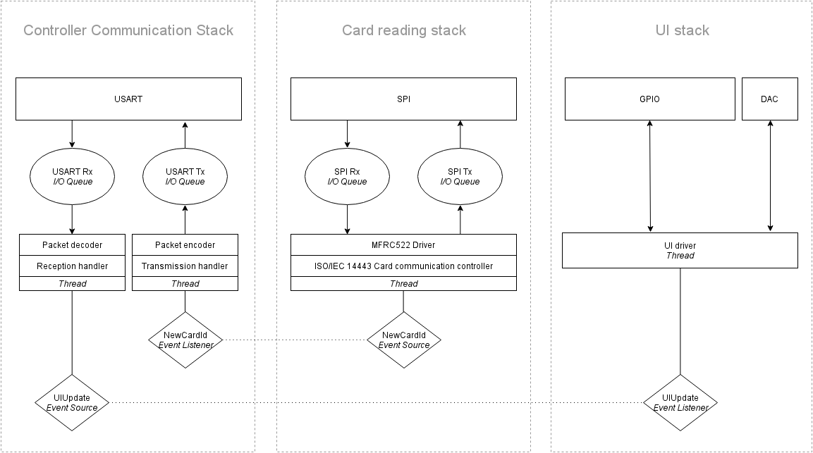
ChibiOS-provided facilities
USART, SPI, GPIO and DAC are peripheral drivers from the ChibiOS/HAL. I/O Queues are communication objects provided by the ChibiOS/RT.
Packet decoder and Packet encoder
Packet decoder reads received bytes and parses them into Packet structures. It also checks checksums and detects transmission corruption. It then hands the received Packet (or errors) to the Reception handler.
Packet encoder gets Packet structures from the Transmission handler, serializes them into bytes, generates appropriate checksums and transmits them.
Reception handler and Transmission handler
Reception handler handler incoming Packets and generates events that other parts of the application listen to. Those events are mainly notifications about UI status change. It also handles reception errors, by calling Transmission handler and asking him to ask the Controller to retransmit the last Packet.
Transmission handler listens to events from the application, primarily event that card reading was successful. It then encapsulates the information into a Packet and hands it to the Packet Encoder. It is then waiting to be notified by the Reception handler that the Controller has acknowledged the reception or asked for retransmission.
MFRC522 Driver
This is the driver that controls the MFRC522 module. It handles its communication protocol and knows what to write to which registers.
ISO/IEC 14443 Card Communication Controller
This is the most important part of the Reader. This module is responsible for communicating with ISIC/ITIC cards through MFRC522 module. It implements ISO/IEC 14443 Card Activation protocol (Anticollision sequence) and can read ID of all cards present in the field. (Therefore, touching reader with your wallet filled with different cards will work (theoretically)).
It generates events that card reading was successful.
UI driver
This driver drives the LEDs and the Speaker. This driver is capable of playing sound samples, not only beeping, as it controls the DAC that the speaker is connected to. It can also measure voltage the amplifier is supplied with and adjust volume accordingly. It listens to events to update the UI state.
UI states corresponding to different situations are also defined in this driver.
UI states
state_failure
Both red LEDs are blinking. This is the state UI is in after reset. As soon as Controller initiates the Reader, the UI state changes to state_idle. If the Controller has not yet initiated communication it may be malfunctioning, so we are notifying user of the failure.
state_idle
This is a normal waiting state for the Reader. Red LED1 is on.
state_open
Green LED2 is on, associated with a long high-pitch beep.
state_deny
Red LED2 is blinking, associated with 3 shorter beeps on a lower frequency.