“The science isn’t about why. It’s about why not!” –Cave Johnson
Why not build a circuit which would add an USART (optionally with USART Bluetooth module) to the kitchen scale?
The idea of this simple hack was born some time ago, when I needed a simple force sensor connectable to a computer for a certain experiment. Looking at a kitchen scale I’ve realized that it has the precision I need (well… there wasn’t need for much of it). Being too lazy to buy a force sensor (they weren’t cheap either; just for one hour of measurement) I’ve built a simple USART interface for the scale. Now I’ve finally found some time to make this mod permanent, despite that it is not needed anymore.
The scale I’ve modded was an ETA 1770 (no longer manufactured). The control circuit contained only through-hole components mounted on a double-sided PCB, and for every component it was easy to find a datasheet! This made the work pretty easy as you could guess how this thing is working just by tracing traces on a PCB and looking into a datasheet. The scale contained a HA17324A quad op-amp, hef4066bp quad analog switch and a p87lpc761b one-time programmable microcontroller. (I’ve been probing around the MCU hoping that the built-in USART or I2C would be outputting some useful data, no luck there.)
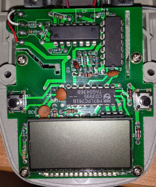
It didn’t take long to realize that the scale contains a ramp-compare ADC, built from the PWM output of an MCU, capacitor, resistor and an op-amp. This was quickly verified by a multimeter with counter, which has shown that the frequency on the PWM pin of MCU was changing and was directly proportional to the applied weight (actually, the pulse width was changing, but the time between the end of a pulse and the start of other was constant). Later, this was also confirmed with an oscilloscope.
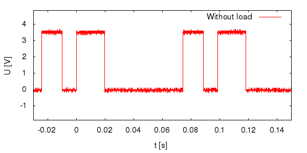
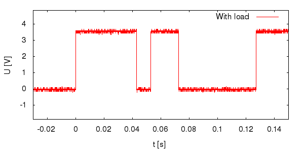
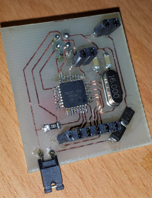
We can see that the MCU produces two pulses, one of which has a fixed length. So it happened that an SMD ATmega8 was lying around in a shelf, unused, sad… So I’ve built a very simple circuit with an ATmega8 MCU, 6-pin connector for an FTDI cable (with cross-linked Rx, Tx, RTS and CTS) or for a USART bluetooth module. The scale is powered by a two 3V button batteries. The maximum operating voltage of the ATmega and of the Bluetooth module is 5.5V. No linear regulator was at my disposal, and I wanted to build this thing from the things that were lying around. So I’ve added 2 diodes in series to drop the voltage. The whole circuit is trivial, one connector for power, one connector for the signal from the scale (connected to the ICP pin on ATmega), FTDI connector connected to USART and an external crystal. You can see the schematics in the project repository.
The coding part was also easy. I’ve just used an Input Capture Unit of the ATmega to measure the pulse length, calculated running average from 10 samples, converted it to string (being lazy I’ve used a printf redirected to USART), added a timestamp and transmitted. The hardware flow control is not yet implemented, but this thing works without it. Why transmit a string from MCU through USART? Seems like a waste of bandwidth. Well, the data throughput is not critical here, and this way this thing does not need any client, just read directly from the bluetooth socket (or redirect it to a .csv file) and you are done. The code is also in the project repository.
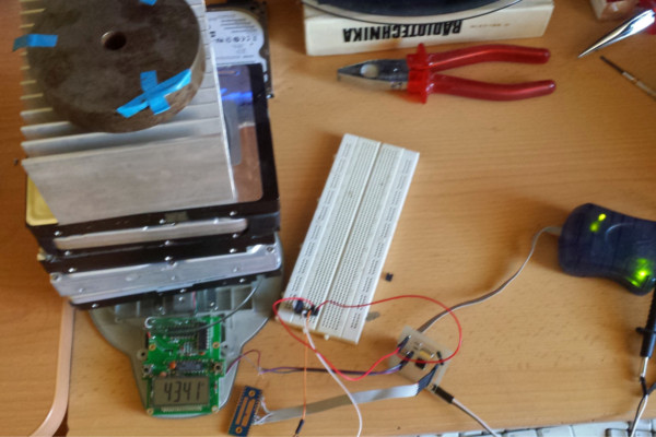
The length of the PWM pulse is directly proportional to the applied weight. It was therefore required to find the ratio of the signal length as opposed to the applied weight. It is always useful to have some hard drives and a large heatsink lying around.
Time to add a bluetooth module. This was plug and play (whoa, the whole thing worked +- on the first try). I needed to change the Bluetooth device name though. Not having an FTDI cable lying around, I’ve just used this snippet of code hoping that it would work:
_delay_ms(1100);                    // There must be a second of silence before the escape sequence is sent
printf("///");                      // Send the escape sequence
_delay_ms(1100);                    // Second of silence after the escape sequence
printf("AT*AGLN=\"Scale\",1\r");    // Change device name to "Scale" and remember it
printf("AT*ADDM\r");                // Go back to the data mode
And surprisingly, it did.
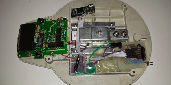
There has been just a little bit of hot-wiring required on the board, the PWM pin also needs to be disconnected when the circuit is not powered on, otherwise the scale won’t work.
The last step was to put it all together, drill a hole in the case for the power switch (just a jumper for now) (because the interface + bluetooth module consumes 35mA as opposed to the scale itself, which only requires 5mA), and glue the cables there. It looks quite messy inside, but from the outside except the small hole you won’t notice a thing.
In time I’ll maybe make an Android app for it.